Image courtesy NASA
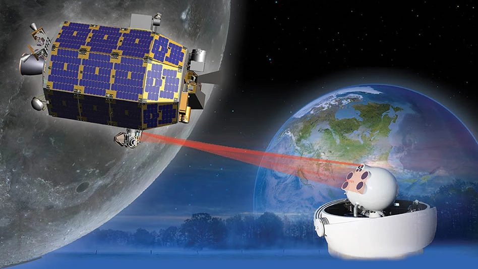
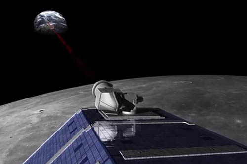
NASA’s Lunar Atmosphere and Dust Environment Explorer (LADEE), pronounced “Laddie,” was a robotic mission launched in 2013 that orbited the moon to gather detailed information about the structure and composition of the thin lunar atmosphere, and the first-ever Lunar Laser Communications Demonstration (LLCD). The LLCD used lasers, not radio waves, like other spacecraft that have flown beyond close-Earth orbit have used, to communicate with controllers on Earth allowing the spacecraft to communicate at broadband speeds with the ground.
The probe was approximately 7.7ft x 4.75ft x 4.75ft, weighing 383kg (844 lb). The probe took about 30 days to get to the moon. LADEE then went through a checkout period for another 30 days. After that, the probe conducted a 100-day science mission and was even able to extend its mission for an additional month.
Once LADEE’s mission was completed, NASA intentionally impacted the probe into the far side of the moon, away from historically important sites like the Apollo landing zones.
Lunar Laser Communications Demonstration
The LLCD was a project undertaken by MIT Lincoln Laboratory, NASA's Goddard Space Flight Center, and the Jet Propulsion Laboratory. It was NASA’s first attempt to demonstrate optical communications between a lunar orbiting spacecraft and Earth-based ground receivers.
All prior communications with spacecraft beyond close-Earth orbits required spacecraft to have small, low-mass, low-power radio transmitters and giant satellite dishes on Earth to receive their messages. LLCD was an alternative process to replace traditional radio communications with specialized lasers and laser detection units to send information between lunar orbit and three receiving stations in the U.S. and Spain.
LLCD demonstrated error-free communication from the moon, including during broad daylight and even when the moon was within 3° of the sun, as seen from Earth. LLCD also operated error-free when the moon was less than 5° above the horizon, as seen from the ground station, which showed that wind and atmospheric turbulence didn’t significantly impact the system. LLCD was even able to communicate through thin cirrus clouds.
The 30-day test was a much more comprehensive check of its utility for all-purpose communication. Rather than simply downloading a pre-arranged file, NASA used the device for real communication with LADEE, and real collection of data. While all LADEE’s science data went to the ground via radio frequency (RF) link, the data sent by the LLCD test was verified against the RF data, demonstrating the feasibility of laser communication uplink/downlink for future missions.
The LLCD used a pulsed laser beam to transmit data over the 239,000 miles from the moon to Earth at a record-breaking data-download speed of 622 Megabits per second (Mbps), versus 75Mbps. This download speed was more than 6x faster than the speed achieved by the best radio system ever flown to the moon and would normally take several days to download.
LLCD also demonstrated a 20Mbps uplink, which was used to loop back error-free high-definition video to and from the moon, important for future human exploration missions, and also provided simultaneous centimeter-class precision ranging to the spacecraft, which can be used to improve the gravity models of planetary bodies.
The testing looked at more than raw download speed, prioritizing signal reliability and accuracy, along with possible distance effects. LLCD worked well even at extremely oblique angles, when the satellite was near the Earth’s horizon and its signals were forced to move through the thickest portions of the atmosphere. The laser signal could be read without error even in broad daylight and through light clouds.
In addition to this lack of error, the LLCD was able to switch from one ground station to the next as the Earth turned, in a manner that NASA compared to how a mobile phone network operates, and the system did so without human intervention. The system could even lock on to the ground stations without using a radio signal.
The real breakthrough of the LLCD demonstration, however, was the spectacular success of its essentially flawless operations, allowing the system to return real, high-value science data from LADEE’s instruments investigating the moon’s environment and showing the promise of laser communication for future missions.
The downside for the future is range. Simply boosting power to the laser to make it cohere better over a longer distance is a losing game. A more reasonable solution, and one NASA is working toward, is the Lunar Communications Relay Demonstration (LCRD). This would see NASA pepper space with laser-routers to read and re-transmit laser signals from a new transmitter. LCRD is aboard the U.S. Department of Defense’s Space Test Program Satellite 6 (STPSat-6) launched December 2021.
Line of sight jitter testing
For laser communications systems, maintaining dynamic stability of the laser beam is critical to maintaining high data rates. Common design requirements are 1/10 to 1/5 of the angular extent of the beam. For the Lunar Lasercomm Space Terminal (LLST) system, a secondary payload and part of the LLCD, the requirement was 4.2μrad RMS, which is very small and challenging to meet. Much time was spent modeling and testing this performance metric to ensure the system could meet it. This required the magneto-hydrodynamic inertial reference unit (MIRU) providing the active stabilization of the optical telescope to support fine pointing of the laser during operation in space to be tested for line-of-sight (LOS) jitter.
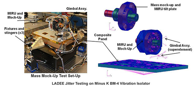
A detailed finite element model was developed to include all major components of the optical module assembly. The purpose of this system model was to capture the structural dynamics behavior of both the overall system and each of the individual optical elements and predict the system’s performance.
The model accounted for the structural dynamics of the system, as well as the active stabilization control. The LOS jitter prediction was generated by integrating the results of the optical, structural, and controls models.
A test bed was developed to measure the jitter from prototype and flight hardware. For initial jitter testing, a telescope mass mock-up was constructed to mount to a real panel gimbal and flexure. The mass mock-up was designed to closely imitate the mass and moment of inertia of the actual optical head. The panel was mounted to a stiff frame which was mounted to a Minus K BM-4 negative-stiffness vibration isolation table.
Testing could not be performed in flight conditions, requiring a system model to verify the ability of the optical module to meet the jitter requirements. The model had to be well correlated to the test data, especially in the frequencies that contributed most toward the residual LOS jitter.
Test equipment limitations prevented the hardware from being driven with the simultaneous 6-axis input spectrum defined for the system. Three stingers were used to excite the Minus K table, and angle rate sensors on the stiff frame were used to measure the input into the panel. Instead, the system could be excited in several, but not all, axes simultaneously.
The data gathered from this testing was used to validate the LOS jitter finite element model (FEM) via direct laser pointing comparisons. The first step in validating the model was to build a FEM representative of the hardware being tested, and of the excitation method. The next step was to match the modal frequencies and mode shapes from the test to the FEM.
The first pass at model correlation showed a 25% difference in frequencies from test to FEM predictions at the modes of interest, where ideally there would be no more than 5%. The bolt stiffness was modified until FEM predictions from the configurations were within 5% of the measured values.
Simplifying the models further verified that the modal frequencies matched, and the mode shapes matched the test data. Even after all these modifications the LOS jitter FEM still didn’t correlate well with the test data.
To finally get the LOS Jitter FEM to agree with the test data, the mass of the fixturing (stiff frame, Minus K table, etc.) had to be included. Additionally, the model had to be loaded with the same 3-point force excitation as the test. By including all these elements, the LOS Jitter FEM finally showed correlation within 5% of test data for the first four modes.
What’s in the moon’s exosphere?
While scientists have speculated on the presence of neon in the lunar atmosphere for decades, the LADEE Neutral Mass Spectrometer (NMS) instrument confirmed that the moon’s exosphere is made up of mostly helium, argon, and neon. Their relative abundance is dependent on the time of day on the moon. While most of the lunar exosphere comes from the solar wind, NMS showed that some gas comes from lunar rocks. Argon-40 results from the decay of naturally occurring radioactive potassium-40, found in the rocks of all the terrestrial planets as a leftover from their formation.
The NMS also revealed an unexpected source of some of the helium in the lunar exosphere. Approximately 20% of the helium is coming from the moon itself, most likely from the decay of radioactive thorium and uranium found in lunar rocks.
The moon's atmosphere is so thin, rocket exhaust and outgassing from spacecraft could easily change its composition. It’s critical to learn about the lunar exosphere before sustained human exploration substantially alters it.
End of LADEE’s mission
LADEE impacted into the moon about 0.5 miles from the eastern rim of the larger Sundman V crater, just 0.2 miles north of the spot where mission team members predicted the spacecraft would go down based on tracking data.
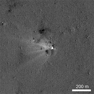
The final impact occurred on April 18, 2014. LADEE was traveling at a speed of 3,600mph at the time of impact into the moon. NASA’s Lunar Reconnaissance Orbiter took a photo of the crater created by LADEE when it impacted.
The image was created by ratioing two images, one taken before the impact and another afterward. The bright area highlights what has changed between the time of the two images, specifically the impact point and the ejecta.
Although the mission was relatively brief, LADEE was highly productive and laid the foundation for faster communication from space to the Earth.
About the author: Steve Varma is president, Minus K Technology. He can be reached at 310.348.9656 or sales@minusk.com.
Minus K Technology Inc. was founded in 1993 to develop, manufacture and market state-of-the-art vibration isolation products based on the company’s patented negative-stiffness technology. The company is an OEM supplier to leading manufacturers of scanning probe microscopes, micro-hardness testers, and other vibration-sensitive instruments and equipment.
Latest from Aerospace Manufacturing and Design
- Taiwan’s China Airlines orders Boeing 777X passenger, freighter jets
- Reamer re-tipping extends life of legacy tooling
- Revitalizing the Defense Maritime Industrial Base with Blue Forge Alliance
- Safran Defense & Space opens US defense HQ
- Two miniature absolute encoders join US Digital’s lineup
- Lockheed Martin completes Orion for Artemis II
- Cylinder CMMs for complex symmetrical workpieces
- University of Oklahoma research fuels UAS development


