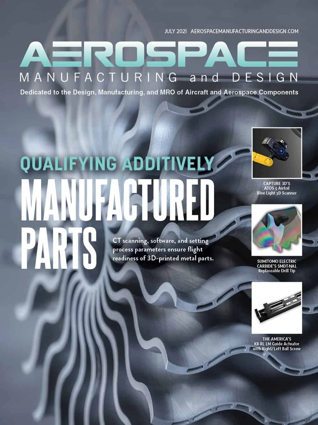
qualifying parts for aerospace takes on special significance when parts are 3D-printed. Metals and polymers used to make 3D-printed components are essentially forged on the fly, so there may be questions about material integrity that must be answered comprehensively and scientifically. Especially with flight-critical parts, the technology used to accomplish this task is computed tomography, better known as CT scanning.
Qualifying
A decades-old technology, CT scanning is a viable way to peer into and through a workpiece to uncover any hidden internal flaws. CT scanning also allows additive manufacturing (AM) users to verify that their equipment is functioning properly and that their processes are sound and repeatable – able to produce the same metallurgical and mechanical characteristics on the parts 3D printed today and a year from now.
CT scanning uses an X-ray source to generate digital slices of an object from multiple angles. Software can then reconstruct the 2D images into a highly accurate 3D model with a corresponding data set suitable for a variety of analyses. Porosity, delamination, cracks, voids, and other defects are clearly visible, as are internal part features that would otherwise require cross-sectioning and other destructive methods to qualify.

Details matter
In aerospace-grade AM metal parts production, laser powder bed fusion (LPBF) processes, including selective laser melting (SLM) and direct metal laser sintering (DMLS), are most used. These technologies also have the most expensive equipment, and due to LPBF’s relatively low build speeds and high material costs, it’s not cost-effective for a manufacturer to print multiple iterations of a full-size workpiece and CT scan each one to determine the perfect process setup.
Instead, manufacturers must develop production operating parameters by printing small test cubes at various locations and orientations within the build chamber. These are then CT scanned for attributes such as material density and consistency, separation between layers, and dimensional accuracy. An operator who finds defects can adjust laser power and other variables, printing multiple test specimens to optimize productivity and part quality.
This process is then repeated with larger parts, and those with complex geometries representative of the target workpiece(s). Design elements such as cooling channels, overhangs, and various wall thicknesses can also be repeatedly evaluated until the metal fabrication process is predictable and productive.
Material commitment
Testing represents a significant investment, well beyond that of the equipment itself. Any metal AM parts provider should adequately budget for testing in terms of production time, raw materials, operator training, and access to CT scanning equipment and software. Expect up to a year of process development for any new 3D printing technology, followed by several months of fine-tuning for each subsequent machine.
Aluminum, titanium, Hastelloy, and Inconel superalloys are widely accepted by aircraft manufacturers, but greater scrutiny is expected and understandable when parts are built or grown via 3D printing rather than machined from billet. There are also new alloys and hybrid powder blends possible, all of which require extensive testing prior to flight use.
CT scanning has shown to be an important tool for the qualification of these and future materials. This is true for the 3D-printed brackets, fuel nozzles, and turbine components made from them and for the raw powder itself. Manufacturers can use CT to analyze high-resolution models of individual grains only a micron or two across, scanning for porosity and irregular grain shapes or sizes that in large enough numbers might negatively impact finished-part integrity.
Contamination is also a concern for manufacturers using metal 3D printing, and it can be avoided only through strict material handling and sourcing procedures. It’s critical to have the means to find contamination when it does occur and identify any uses of recycled powder. These occurrences are easy to spot with CT scanning, with faults appearing as bright spots within the part image.

Scaling up
Use of metal AM in aerospace is poised to grow throughout the coming decades. The design freedom and opportunities for lighter, stronger, and more fuel-efficient components easily offset the obstacles. Furthermore, 3D-part printing will become more efficient.
AM equipment manufacturers continue to deliver machines that are faster, more accurate, and simpler to use, while CT scanning providers and software firms are keeping pace by developing complementary systems. One example is software-based mesh compensation. Though not focused on any specific industry, it reduces the number of iteration cycles during the design phase of additively manufactured parts, anticipating distortion and automatically compensating for it within the part geometry.
Build strategy also plays a role. For instance, the means to dynamically adjust beam size, power, and traverse speed can profoundly impact part quality. Therefore, it’s critical to establish a feedback loop between the as-scanned and as-designed part models, comparing the two and optimizing build parameters to minimize differences.
Volume Graphics and its parent company Hexagon continue to work closely with customers, material providers, and metal AM equipment producers to connect various software tools used during the manufacturing process and share data seamlessly in real-time. This includes the CAD system used to design the additively manufactured parts, simulation software used to model performance, and inspection software to examine and analyze the final workpiece. By closing the loop on these systems, aerospace manufacturers will have the ability to design and produce better parts more quickly, more efficiently, and more consistently.

Explore the July 2021 Issue
Check out more from this issue and find your next story to read.
Latest from Aerospace Manufacturing and Design
- AIX shows aircraft interiors are a strategic priority for global airlines
- Machine Tool Builders Roundtable: Turn equipment into expertise
- No time to waste: How to machine MedTech parts more efficiently
- The 5 Best and Fastest Spindle Repair Services
- Mill smarter, not harder: How collaboration optimizes production
- Be proactive – stay ahead of tariffs and other economic and supply chain curveballs!
- Taiwan’s China Airlines orders Boeing 777X passenger, freighter jets
- Reamer re-tipping extends life of legacy tooling


