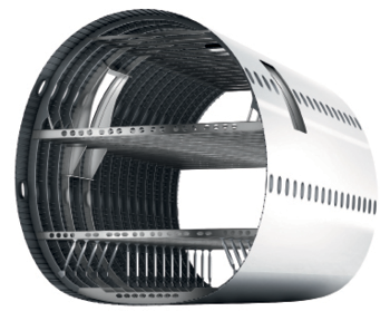
Lightweight, high-tensile-strength fiber composite materials are essential to modern aircraft construction, but machining such compounds – especially those formed from multi-material stacks – is particularly demanding.
Many fuselage and wing parts are manufactured from carbon-fiber reinforced plastics (CFRP) where the most common machining application is drilling rivet holes, as riveting continues to be an important connection method for aircraft due to its reliability. However, cutting through delicate carbon fibers using a drill is not simple, because these fibers tend to tear. The fibers are also highly abrasive, so conventional cutting edges blunt rapidly.
Drilling becomes even more challenging because the composite material is often arranged in stacks made of CFRP and metal layers. CFRP/Ti, CFRP/Al, and CFRP/Ti/Al combinations are common in door frames, formers, and reinforcement profiles. During drilling, the tool comes into contact with materials that have a wide range of different properties. Complying with the strict diameter tolerances – usually around 40µm (0.0016") – for all of the material layers is no easy feat. This is particularly difficult with a large ratio of depth of the drilled hole to the required diameter.
Vibration drilling has proven to be effective. With a vibration unit fit to a machining center, standard feed movement is complemented by an oscillating action (sinusoidal oscillation) in the drilling-tool feed direction. The unit usually contains a wave washer and a bearing, so one part remains fixed while the other rotates. Vibration frequency values and the amplitude depend on the design. If large fuselages or wing parts no longer fit on a machining system or are difficult to access, the aircraft fitters work with mobile, semi-automatic drilling machines, which are now available with vibration units.
“Vibration drilling is a particularly good option if the first layer to be drilled into is CFRP, followed by the metal layer,” Stefan Benkóczy, aerospace component manager for the tooling provider, Walter, explains.
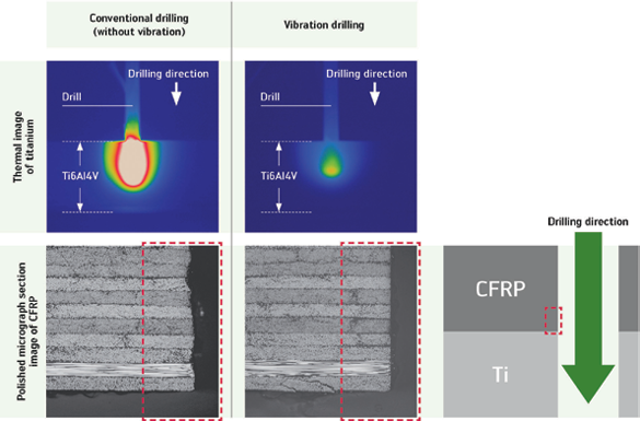
This method aims to use the tool’s longitudinal oscillations to produce short metal chips without increasing the process time, as is the case for pecking (chip removal feed strokes). During oscillation, the tool is not cutting constantly, causing a break in the chip length. Long chips can rub against the wall of the hole drilled into the CFRP when being transported back through the drill’s helical flutes, and at worst, may wear down this wall beyond the tolerance limit of the drilled hole. Chips broken off when they are short cause less damage. In addition, short chips can keep machining temperatures down.
“The deformation energy is mainly transferred to the chips, resulting in an increase of their temperature. But short chips are removed in an optimum manner, therefore the process temperature is halved for vibration drilling compared to conventional machining using minimum quantity lubricant (MQL),” Benkóczy explains.

Vibration drilling protects the composite material matrix and minimizes diffusion wear on the tool, increasing component quality.
“Tool life is also increased while the process time remains the same,” Benkóczy notes.
In order to achieve the best results, process parameters – cutting data, vibration frequency, amplitude, tool cooling, geometry, and other factors – must be carefully matched to the application and the available equipment. With conventional mechanical vibration units, the drill’s oscillation frequency depends on its rotational speed. A 500rpm to 3,000rpm speed is a feasible range for a drilling diameter of around 5mm. Wave washers that produce 1.5 or 2.5 longitudinal oscillations per revolution result in a typical frequency range of approximately 12Hz to 125Hz. A large amplitude increases tool wear and can lead to tool breakage.

“In order to avoid placing unnecessary stress on the tool, the amplitude must be selected so that the chips break off straight and cleanly.” Benkóczy says. “However, in the case of unstable clamping arrangements, the amplitude must be significantly increased to ensure that the chips still break off.”
Special machining methods require special tool solutions. Drills with PCD cutting edges or a diamond coating, such as those normally used for machining composites, are only an option for vibration drilling under very specific conditions. The extremely hard diamond cutting materials are generally too brittle for this application.
Suitable for vibration drilling, Walter’s Titex VFT1A drills include four lands to ensure that the drill remains on course, particularly when drilling through layers of different material. An aluminum-chromium-nitride coating protects the drill from wearing quickly, and its internal coolant channels are designed to provide the MQL.
“Vibration drilling in composite stack materials increases process reliability. Short chips are evacuated in an optimum manner and there is reduced variation in the diameters. In conjunction with an automated system, vibration drilling represents a very economical alternative to conventional drilling,” Benkóczy concludes.
He notes that there is still potential for further improvement in this area.
Walter USA LLC

Explore the April May 2016 Issue
Check out more from this issue and find your next story to read.
Latest from Aerospace Manufacturing and Design
- Revitalizing the Defense Maritime Industrial Base with Blue Forge Alliance
- Safran Defense & Space opens US defense HQ
- Two miniature absolute encoders join US Digital’s lineup
- Lockheed Martin completes Orion for Artemis II
- Cylinder CMMs for complex symmetrical workpieces
- University of Oklahoma research fuels UAS development
- Motorized vision measuring system
- Everyone's talking tariffs


