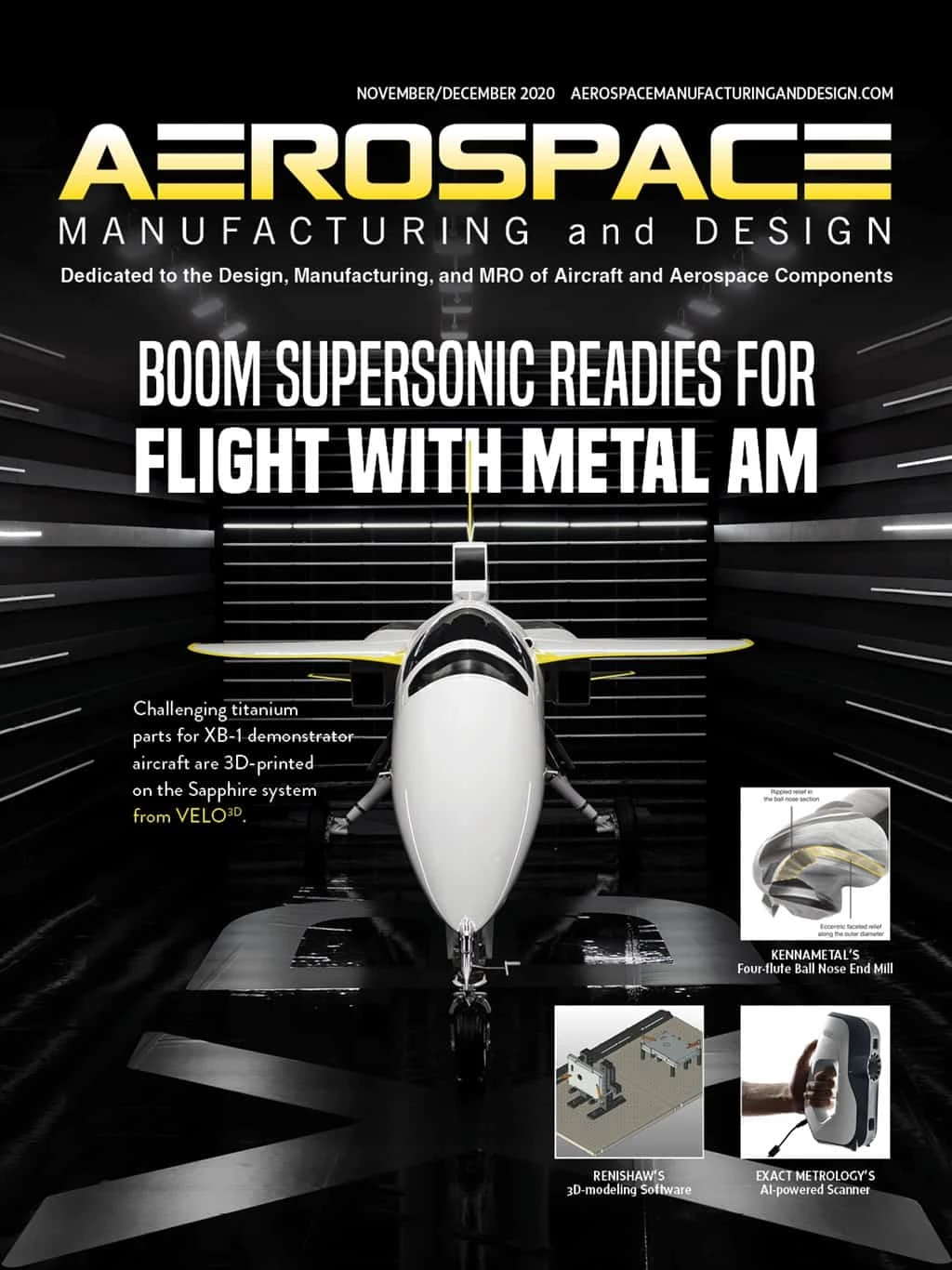
The XB-1 is Boom Supersonic’s demonstrator aircraft, unveiled in October 2020, that brings the return of supersonic air travel closer to reality. Slated to begin flight testing in 2021, XB-1 is a one-third scale demonstrator for the full-sized Overture airliner scheduled to debut in 2025.
Early in the project, Boom Supersonic’s design and engineering team studied additive manufacturing (AM) to produce some of their most complex part designs.
“There are many reasons for choosing AM technology over others,” says Boom Engineer Byron Young. “Much of the time and effort in aircraft design goes into joints, the interfaces between components. By designing directly for AM, we can reduce the number of parts and joints, which also reduces time and effort. And part consolidation cuts significant weight.”
Geometric freedom
Many of Boom’s 3D-printed parts channel air using complex vanes, ducts, and louvers. Some of the air routed through these parts exceeds 500°F.
“If fast moving air is touching it, we care about that surface from an efficiency and performance standpoint,” Byron says. “So, when designing these parts, you generally start with aerodynamic profiles and then trim, fillet, and thicken surfaces to create the solid part. The resulting parts are very complex – they definitely needed to be fabricated through AM.”
VELO3D Applications Engineer Gene Miller worked closely with both Boom Supersonic design engineers and Duncan Machine Products (DMP), the supply chain partner that handled printing and post-processing.
“The unique types of geometries Boom created for directing flow, with a focus on weight savings, couldn’t be done with sheet metal or casting or any other way,” Gene says. “To reap the benefits of complex design and weight reduction together, the only option was to do it with metal AM.”
Having worked with VELO3D on trial parts in 2019, the Boom Supersonic team chose the company’s next-generation laser powder-bed fusion (LPBF) technology to produce:
- Printed titanium manifolds for the variable bypass valve (VBV) system that routes air released by the engine compressor to the aircraft’s outer mold line (OML)
- Exit louvers for the environmental control system (ECS) that cools the cockpit and systems bay
- Louvers that direct the center inlet’s secondary bleed flow to the OML
- NACA ducts and two diverter flange parts. NACA ducts are often used in high-speed aircraft to capture exterior air and channel it into the aircraft to cool the engine bays.
All parts were printed on the VELO3D Sapphire system. In almost every case, the Sapphire was able to print parts directly from Boom’s CAD data, preserving original design intent.
“We did use our system’s Flow pre-print software to add some structural ribbing on the thinner walls of the NACA ducts that had to be constrained,” Gene says. “But for the most part the other components all printed as-is, with no compromise to the design.”
Byron from Boom was impressed with Sapphire’s ability to accurately produce the extremely thin-walled parts. “The Sapphire system allowed us to print walls as thin as 20 thou (0.02" or 750µm), with a surface finish that didn’t require additional machining in most cases.”
The high height-to-width aspect ratio made possible by the VELO3D machine’s non-contact recoater system – which distributes each new layer of powdered metal to be fused by dual lasers – was another plus. To remove mass, the vanes on the center inlet’s bleed louvers were printed hollow, and the parts were designed with thin walls along long spans.
“Because our technology can print that very high aspect ratio in this kind of design, we didn’t need excess material for strength inside the structures, and we could grow those duct vanes up very high without any interference from the recoater,” Gene says.
Titanium
One of the project’s big challenges was working with the titanium material Boom chose for the 3D-printed parts.
“A positive aspect of using titanium is the material allowables at temperature,” says DMP Additive Manufacturing Engineer Aaron Miller (no relation to Gene). “There’s less loss of strength at high temperatures compared to aluminum or carbon fiber, and it has a higher strength-to-weight ratio.”
But lightweight, extremely heat-resistant titanium can be delicate and difficult to work with, no matter how it’s manufactured. If titanium is cooled too rapidly, it becomes brittle and is prone to cracking.
Titanium parts can be manufactured conventionally via casting, which has a slower cooling rate to prevent cracking, Gene notes. But the extremely thin walls in the aircraft hardware designs would have been nearly impossible to cast.
“That’s really one of the driving forces behind using 3D printing for these parts because we can print large, thin-walled titanium sections without the high scrap rate of cracked cast parts,” Gene says.
He acknowledges the learning curve. “Boom designed a part family that was new to us, really pushing the envelope for weight reduction and thin-wall geometries, and we had a lot to learn as far as printing these components from titanium and what to expect from the physics of printing. How is it going to move? What can be printed without supports? What areas needed support?”


Process control is critical
VELO3D’s AM process optimizes the print parameters and sequences to produce robust titanium parts.
“This reduces the amount of internal stress in the substrate as the material is being deposited in the Z build-direction,” Gene explains. “It diminishes the possibility of cracking by mitigating internal stresses formed during cooling.”
Quality control is integrated throughout the entire build, starting with Flow pre-print software, executed through the Sapphire system, and validated with Assure’s quality assurance. Pre-build machine calibration is achieved with a single click, automatically checking laser alignment, beam stability, and powder-bed quality. In-process metrology monitors key metrics and flags anomalies. Comprehensive build reports for all parts are compiled for future reference.
Once Boom’s titanium parts were 3D printed, they were sliced off the build plate with sawing or wire-cutting EDM. The DMP machinists found post-processing to be relatively straightforward.
“After cutting off the build plate, we had very little to do in the way of post-machining apart from minimal support removal,” Aaron says. “You don’t have any tiny supports in small crevices or hard-to-reach places because the SupportFree technology eliminates the need for those. Parts come out of the Sapphire system almost finished, just needing a little handwork with a screwdriver or grinder. We also ream out pilot holes (on larger parts to be joined) with a mill to ensure they’re the correct size. It’s part-dependent, but probably just a half-hour of machining per part, which is not a big deal.”

Part geometries brought an additional challenge when creating fixtures to hold the parts during finishing. Aaron adds, “There’s almost no surface that’s perfectly flat or round on an aircraft, which makes them difficult to grab on to. But we used the parts’ CAD models and quickly designed and 3D-printed custom plastic fixtures (on a separate FDM printer) that were appropriately squared or rounded for us to grab with our finishing tools.”
Part finish out of the machine was tested with a profilometer, registering about 250Ra on average.
“If the customer wanted to go to 125Ra it would take just a few minutes with a vapor hone to achieve that,” Aaron says.
Finished parts were heat treated and/or hot isostatic press (HIP)-processed to enhance fatigue life. “Supersonic flight introduces a number of different phenomena and stresses you generally don’t see with conventional air travel,” Gene notes.
“The main forces being applied aren’t generally pressure loads from breaking the sound barrier,” Byron adds. “In many cases, it’s an induced strain caused by the overall structure of the aircraft flexing around your part. Parts with dissimilar thermal expansion coefficients mounted to each other can produce significant stresses. Designing these 3D-printed parts to be very thin and flexible can actually mitigate some of these issues.”
Try, learn, and iterate
The companies that successfully produced the 3D-printed parts for Boom Supersonic’s XB-1 supersonic demonstrator learned a lot from their collaboration. The Boom team found that AM was more complex than they had envisioned but could also deliver on their original design intent. Duncan Machine Products expanded their 3D-printing expertise significantly, eventually purchasing a third Sapphire machine. “We’re getting a lot of new business because of our capabilities in additive manufacturing,” Aaron says.

Explore the November December 2020 Issue
Check out more from this issue and find your next story to read.
Latest from Aerospace Manufacturing and Design
- Talking machine tools with the professionals who build them
- Tools and strategies for improving your machining processes
- America Makes announces QTIME project call
- Innovation meets precision for 40% faster machining
- Upcoming webinar: Pro tips from a supply chain strategist
- Heart Aerospace relocates to Los Angeles
- Fixtureworks introduces Stablelock Clamps
- Piasecki acquires Kaman's KARGO UAV program


