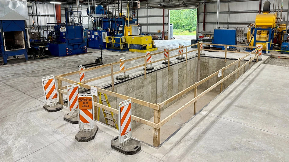
 The result of extremely high rotational energy of jet engine components is evident by the Spin Test Chamber after a burst test. Soft metal bricks, within the test chamber, clearly show the damping effect it has on fragments. Hydraulic lid locks provide additional safety against axial forces. The result of extremely high rotational energy of jet engine components is evident by the Spin Test Chamber after a burst test. Soft metal bricks, within the test chamber, clearly show the damping effect it has on fragments. Hydraulic lid locks provide additional safety against axial forces. |
High-speed rotating components, such as those in the gas turbine, turbo machinery, and the flywheel energy storage industry, must be designed robustly to prevent failures that release lethally high energy, causing catastrophic damage or even fatality.
As an example, a single fan blade on a typical engine powering the Boeing 747-4 engine is about 30" long and rotates at a speed of more than 3,000rpm; this part produces energy to lift a large bus 20ft up in the air. The disk that holds these blades has more than 20 times that energy. Containing the energy of an aero-engine rotor burst is analogous to containing explosives. Thankfully, uncontained engine failures occur rarely in the field, due to rigorous design practices, strictly controlled manufacturing standards, and extensive qualification testing to understand and validate the conditions that lead to damaging failures.
OEMs and component manufacturers can evaluate the performance of flight-critical or safety related discs, blades, and rotor assemblies in a spin testing machine or rig. Test systems allow engineers to evaluate the integrity and performance of rotating components under intense centrifugal loading. These tests can be conducted at ambient or elevated temperatures to simulate engine conditions and observe creep-driven damage failure mechanisms. Advanced instrumentation, such as non-contact sensors or rotating frame instrumentation via slip rings or telemetry, is also available. Implementation of high-speed video can also capture the detailed behavior of a rotor in the instance of a burst event.
Due to the large amount of rotational kinetic energy accumulated in rotating components, spin testing brings inherent risks. Often the burst tests are carefully planned to validate or demonstrate component failure conditions; however, it is not uncommon for rotors to fail unexpectedly, posing an inherent danger to both equipment and personnel. Unfortunately, recorded cases of unexpected disc bursts during spin testing have occurred, causing significant property damage and even death.
Designing a spin testing machine that can contain high-energy rotor bursts safely poses significant engineering challenges. A common approach for this type of equipment is to provide a liner that covers the area of the fragment impact, such that it can withstand energy imparted by various fragment sizes and impact areas (at the thickness provided).
This seems like a logical approach, but it assumes that the user of the equipment knows, and is capable of predicting, the shape of burst fragments and the manner in which they will affect the liner. In fact, the behavior of a bursting disc is very unpredictable and the burst fragments will have varying geometries. The shape and size of these burst projectiles will significantly affect the kinetic energy it contains, and their ability to penetrate a containment barrier.
 Hydraulic safety locks are a precaution for pulverization and other bursts, which contain a strong radial element. Hydraulic safety locks are a precaution for pulverization and other bursts, which contain a strong radial element. |
Engineers, at Hudson, Mass.-based rotational testing company Test Devices Inc., have developed a comprehensive approach that combines modern engineering methods and actual empirical data from burst events conducted in their facility to evaluate the ways rotors fail and the types of damages they could cause.
“Our analysis and experience show rotor energy is only a crude measure of the hazard presented by a burst. The shape of the fragments and their orientation play a surprisingly important role,” says Eric Sonnichsen, founder, Test Devices.
For this reason, the company’s engineers consider a broad range of possible hazards as they design spin test chambers to prevent dangerous fragments from escaping the test machine and causing damage.
“One can imagine how much damage it can cause in the event of disc burst, so we are very serious about designing a structure that can contain it safely and conducting tests without destroying equipment or inflicting bodily harm,” says Hiro Endo, vice president of engineering, Test Devices.
This combination of practical experience and analytical evaluation uncovered some myths in the common approach to evaluating and designing for safe burst testing. The most ground breaking of these is the assumption that containment can be rated for a maximum energy of burst, and therefore, any rotor that bursts at or below that limit will be contained.
“Historically, the tri-hub burst has been the standard used to calculate radial burst fragment energy, but the truth is that it is not the worst failure mode of a bursting disc and it is surprising how infrequently the tri-hub mode occurs in the many tests we perform in our testing facility,” Endo states.
“Another inaccurate belief states that multiple thinner walls spaced apart from one another are more effective than a single wall of equivalent thickness,” adds Rob Murner, president, Test Devices.
The company’s analysis and experience show that a single-thickness wall is able to contain fragments in a better manner.
Finally, the belief that the main concern for containing a burst event is radial leads to the presumption that machines can be operated safely by merely installing them in the ground. There are a number of recorded cases where some burst fragments were redirected axially with very high force. Poorly designed inner liners are particularly dangerous because they actually direct high-energy fragments into the lid. Multiple accidents have involved the ejection of the spin testing machine-cover in the vertical direction, resulting in the destructive escape of high-energy fragments.
Test Devices has a vast amount of experience and has collected volumes of data from past tests. This information, combined with published ballistics impact research, has formed the basis for the company’s detailed modeling and predictive analysis efforts.
 Test Chamber Diagram: A) Armor liner thickness depends on size, shape, speed, and energy of the rotating part. B) Soft metal liner dampens fragment impacts. C) Top/bottom ledges prevent axial deflection. Test Chamber Diagram: A) Armor liner thickness depends on size, shape, speed, and energy of the rotating part. B) Soft metal liner dampens fragment impacts. C) Top/bottom ledges prevent axial deflection. |
“We have developed a fundamental understanding of burst containment. While we need to provide cost-competitive testing machines, human safety remains the primary criterion in the design of Test Devices spin test machines,” Murner says. “Our efforts have given us a better understanding of burst containment, a method for the analysis of specific burst scenarios and validation of our design practices.”
Spin-test equipment often lasts 30 to 40 years, so machines live to see part sizes and testing speeds that may be far in excess of their initial or intended use. Any machine testing high-energy components requires a design for all eventual uses and be part of a safe plant layout.
Design of robust containment structures and machine features is only the first step in preventing test accidents. Each test is unique and must be engineered to mitigate the hazardous risks inherent in the type of test. Instrument connections into the test chamber require a design to prevent loss of vacuum and fire hazard. High-energy rotors must not be tested with inadequate containment. These scenarios, and other potential dangers, require consideration and carefully review for every test. Design of a strong containment system is only the first step in preventing test accidents. A successful rotor burst test and management of its inherent risk requires expert knowledge and diligent effort in paying attention to details.
“As a testimony to our expertise, Test Devices has successfully demonstrated containment through the testing of major gas turbine engines’ biggest discs,” Endo says. “We can confidently say our containment system is proven and has repeatedly demonstrated its reliability.”
Test Devices’ spin test machines also incorporate proprietary materials and design elements that separate the company level of containment from the competition.
“Our methods are evolving all the time,” Endo states.
Containment and successful safety planning benefit not only the testing organization, but they also enhance the aerospace and aviation industries by improving safety, testing quality, and industry efficiency, as well as performance during the component development process.
Test Devices
Hudson, Mass.
www.testdevices.com

Explore the May June 2013 Issue
Check out more from this issue and find your next story to read.
Latest from Aerospace Manufacturing and Design
- Build your Controlled Unclassified Information (CUI) toolkit
- Michigan Advanced Air Mobility (AAM) Initiative established
- Threaded adjustable grippers
- GKN Aerospace accelerates additive fabrication for fan case mount ring
- Expanded offering of internal coolant live tools
- #47 Lunch + Learn Podcast with INSACO
- Doncasters’ Groton expansion reaches major milestone
- Hardware-encrypted drive with trusted supply chain


